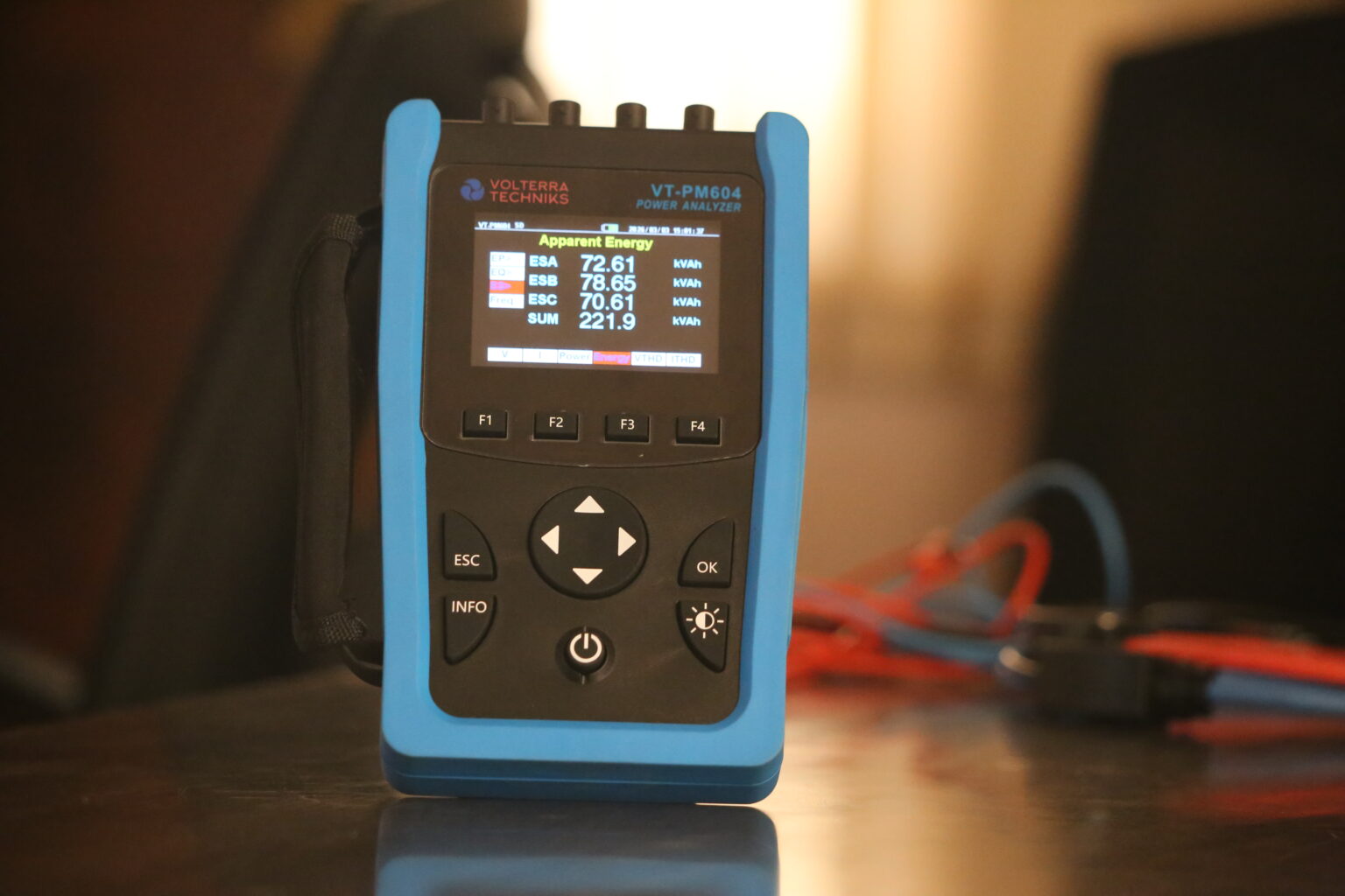
Power Analyzer : How to Use & Industrial Applications
Learn how a power analyzer works, its working principle, measurement process, harmonic analysis and industrial applications. A complete technical guide for engineers, maintenance teams and energy auditors.
How Does a Power Analyzer Work?
In today’s electrically driven industries, simply measuring voltage or current is no longer enough. Modern electrical systems demand accurate monitoring of power quality, energy efficiency, harmonics, and equipment performance. This is where a Power Analyzer becomes one of the most important diagnostic tools for engineers and maintenance professionals.
A power analyzer is designed to precisely measure and analyze electrical parameters in real-time. It helps industries monitor energy usage, troubleshoot electrical problems, evaluate system efficiency, and maintain stable power quality. From industrial manufacturing plants and EV testing labs to solar power systems and motor diagnostics, power analyzers are widely used wherever electrical performance matters.
Understanding the working principle of a power analyzer helps users not only operate the instrument effectively but also interpret measurement data more accurately for diagnostics and energy optimization.
Why Do We Use Power Analysers
The core working principle of a power analyzer is based on continuously sampling voltage and current signals from an electrical circuit and digitally processing these waveforms to calculate electrical parameters.

A power analyzer simultaneously measures:
– Voltage & Current waveform
– Frequency and Harmonics
– Power factor
– Energy consumption
Using high-speed Analog-to-Digital Converters (ADCs) and Digital Signal Processing (DSP), the analyzer converts analog electrical signals into digital data and performs mathematical calculations in real time.

The analyzer then displays calculated values such as:
– Active Power (kW)
– Reactive Power (kVAR)
– Apparent Power (kVA)
– Power Factor
– Total Harmonic Distortion (THD)
– Energy Usage (kWh)
Unlike basic meters, a power analyzer studies the complete waveform behavior instead of only measuring RMS values.
Main Components of a Power Analyzer
Understanding the internal components helps explain how the analyzer performs accurate measurements.
Voltage Sensors
The voltage sensors (or probes) measure the system voltage waveform continuously.
Power analyzers can be used to measure voltages in different types of systems, some of which are:
– Single-phase
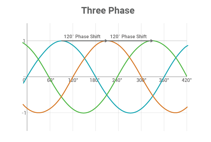
– Three-phase
– AC
– DC
– Line-to-line voltage
– Line-to-neutral voltage
High-end analyzers can also include isolation and protection circuits for operator safety.
Current Sensors / Current Clamps
Current measurement is performed using:
– Clamp-on current transformers (CTs)
– Hall-effect sensors
– Rogowski coils
– Precision shunt resistors
These sensors convert current flow into measurable electrical signals without interrupting the circuit.
Display and Data Logging System
The processed data is displayed on the analyzer screen in real-time through:
– Numeric readings
– Waveform graphs
– Harmonic spectrums
– Trend charts
– Vector diagrams
Modern analyzers also include:
– Internal memory
– USB export
– Ethernet/Wi-Fi connectivity
– Cloud integration
– Reporting software
These features help engineers perform long-term energy monitoring and power quality analysis.
How to Use a Power Analyzer
Using a power analyzer correctly ensures accurate readings and safe operation.
Step 1: Identify the System Type
Determine whether the system is Single-phase/Three-phase/AC or DC in order to pick the right Power analyzer. Then find the wiring configuration of your system (3P3W/3P4W/etc.) and configure the same in the Power Analyser settings.
Step 2: Connect Voltage Leads
Connect voltage probes to the appropriate terminals according to the selected wiring configuration:
Phase-to-phase
Phase-to-neutral
Ensure proper voltage range selection according to the type of voltage probe used.
Step 3: Attach Current Clamps
Select your current clamps according to the current values in your system and connect them correctly.
Improper clamp orientation can produce incorrect power factor readings.
Step 4: Configure Measurement Parameters
Set the correct ratios for your current and voltage probes in your Power Analyser and select the base frequency (50/60Hz)
Step 5: Start Monitoring
If needed, start recording and set appropriate recording intervals and duration.
Long-term monitoring can reveal hidden electrical problems.
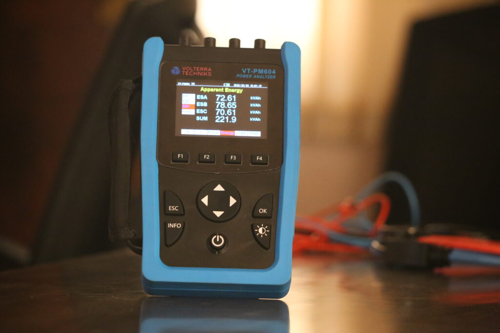
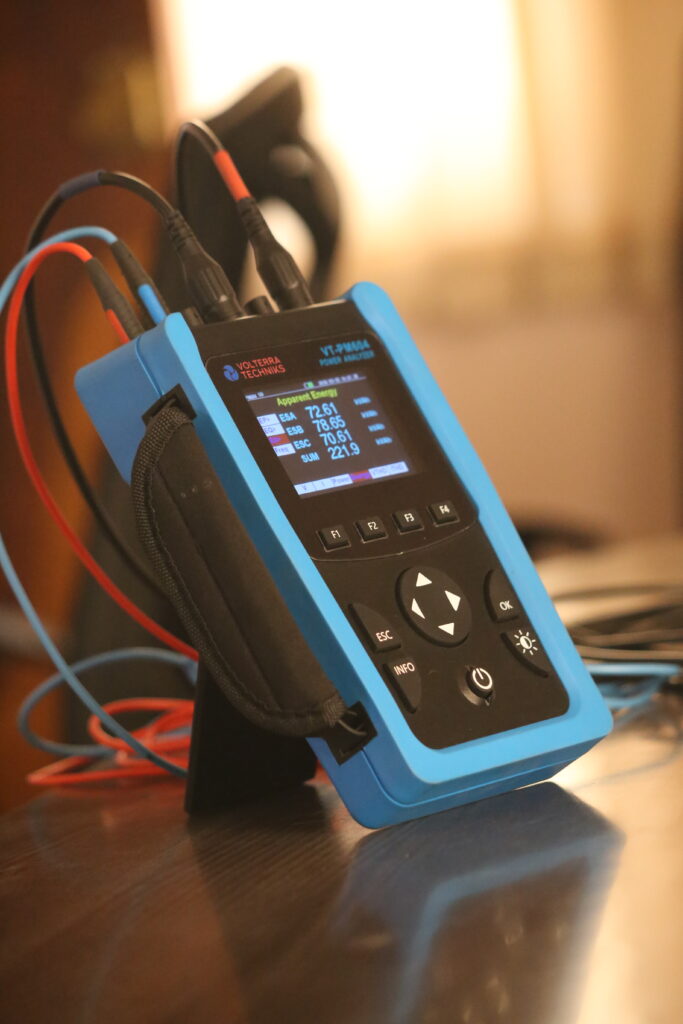
Common Reasons for Errors in Power Analyzer Measurements
01
Incorrect Wiring Configuration Setting
One of the most common causes of inaccurate readings in a power analyzer is selecting the wrong wiring configuration during setup. Modern analyzers support multiple configurations such as single-phase, three-phase three-wire, and three-phase four-wire systems. If the selected configuration does not match the actual electrical network, the analyzer may calculate incorrect voltage, current, power factor, or energy values. This can also lead to phase imbalance errors and inaccurate harmonic analysis. Always verify the system type and wiring diagram before starting measurements.
02
Incorrect Voltage/Current Probes Selected Within Settings
Power analyzers require proper probe configuration to ensure accurate scaling and measurement calculations. If the analyzer settings do not match the connected voltage probes or current clamps, the displayed readings can become significantly inaccurate. For example, selecting a lower current clamp ratio than the actual probe may show incorrect current and power consumption values. Similarly, incorrect voltage range selection may affect waveform accuracy and harmonic analysis. Always confirm probe type, clamp ratio, voltage range, and sensor specifications within the analyzer settings before testing.
03
Loose Connections in Probes
Loose or unstable probe connections can introduce fluctuating signals, intermittent readings, and measurement instability during power analysis. Poor contact between voltage leads, terminals, or current clamps may create electrical noise and inaccurate waveform sampling. In industrial environments with vibration or high electromagnetic interference, loose connections can also lead to transient spikes or missing data in harmonic analysis. To avoid such issues, ensure all probes are firmly connected, terminals are tightened properly, and cables are inspected for damage before performing measurements.
04
Reversed Direction of Current Probes
Current probes or clamps are polarity-sensitive devices, meaning they must face the correct current flow direction. If a current clamp is installed in reverse orientation, the analyzer may display negative power readings, incorrect power factor values, or inaccurate phase relationships. This issue is especially critical in three-phase systems where power calculations depend on proper phase alignment. Most current probes include directional arrows indicating current flow. Always ensure the arrow points toward the load side of the circuit for accurate measurement results.
05
Phase Mismatch in Voltage and Current Probes
A phase mismatch occurs when voltage probes and current probes are connected to different phases unintentionally. For example, if the voltage probe is connected to Phase R while the current clamp is installed on Phase Y, the analyzer will calculate incorrect power, reactive energy, and phase angle values. This mismatch can severely affect power factor calculations and harmonic analysis results. In three-phase systems, maintaining correct phase pairing between voltage and current channels is essential for reliable diagnostics and accurate power quality measurement.
FIND THE BEST PRODUCT FOR YOUR APPLICATION
To Know More
About our VT-PM604, click the link below